PassMark Inline PSU Tester FAQ
What are the important safety precautions?
- Remove anything conductive from your hands (e.g. metal rings, watches, or bracelets) before testing a PSU or working inside your computer.
- Only use the original cables that comes with the tester. The PCIe cable that comes with the tester, is not a standard cable and is custom-made for the tester. Using other cables could lead to short circuit between the voltage rails.
- Make sure all the cables are fully inserted. A loose connection introduces more electrical resistance which can lead to melting of the wires under high load (or even a fire).
- In the case of a dramatic failure of the device under test, you may see smoke coming from the power supply or inside the case or smell a burning. In this case unplug the power supply from the wall. Do not touch the PSU or the PSU Tester in such circumstances.
- Always have someone monitor the testing in case the device under test suddenly fails. Do not start a test and walk away.
- If the PSU Tester is inline (connected to both power supply and motherboard), do not power up using the keypad on the tester. Instead, use the PC power button. This is just a precaution against poor engineered power supplies that do not meet ATX standards and can prevent a short on the PS_ON line.
How do I connect the cables?
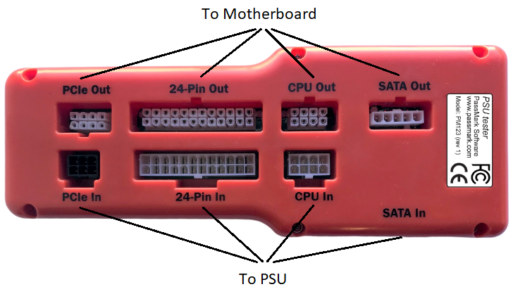
- The picture below shows how to connect the tester to a PSU and motherboard using the cables.
-

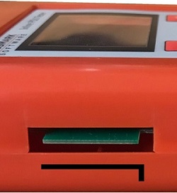
- The “SATA In” terminal is located on the side of the device. This connector is a bit tricky as you have to make sure that it has a correct orientation. The ¬ shape of the SATA power cable should face down (See the below picture).
-

When in inline mode, how should I turn on the PC?
- If the PSU Tester is inline (connected to both power supply and motherboard), do not power up using the keypad on the tester. Instead, use the PC power button. This is just a precaution against poor engineered power supplies that do not meet ATX standards and can prevent a short on the PS_ON line.
My PC fails to boot when the PSU tester is inline. What should I do?
- First check that all cables are connected properly and fully inserted.
- Make sure the “SATA In” cable is plugged and it’s orientation is correct.
- Make sure that you turn on the PC using the “standby” button from the computer case and not using the keypad.
- If the issue persists, disconnect all the cables to motherboard and force power up by keypad to troubleshoot.
What does the background colour of the PASS/FAIL indicators mean?
- PASS means voltage is currently within the approved limits and never been outside the specifications.
- PASS means voltage is currently within the approved limits, but an over-voltage was detected previously.
- PASS means voltage is currently within the approved limits, but an under-voltage was detected previously.
- FAIL means voltage is outside the approved limits.
The background colour of PASS/FAIL messages can be green, red, light red and yellow. Each colour has a different meaning which are explained below:
How can I stress test a PSU?
- We suggest running BurnInTest on the motherboard during inline testing to ramp up power usage by the motherboard and place more load on PSU. The recomanded set of test
What is the maximum current/power limit in inline mode?
| Rail | +12V1 | +12V2 (12V CPU) | +12V PCIe | +5V | +3.3V | +5VSB | +12V SATA | +5V SATA | +3.3V SATA |
|---|---|---|---|---|---|---|---|---|---|
| Max Current | 25A | 50A | 30A | 30A | 30A | 8A | 5.5A | 5.5A | 5.5A |
| Max Power | 300W | 600W | 360W | 150W | 99W | 40W | 66W | 27W | 18W |
The above ratings correspond to a hypothetical 1600W PSU. But in practice most systems don't come close to using this much power on each of these rails. When a desktop computer systems uses more than 700W, it is typically as a result of multiple high end video cards being installed (and multiple PCIe rails are required in this case). See also the question below about testing multiple GPUs.
What are the timing T1, T2, T3 and T6?
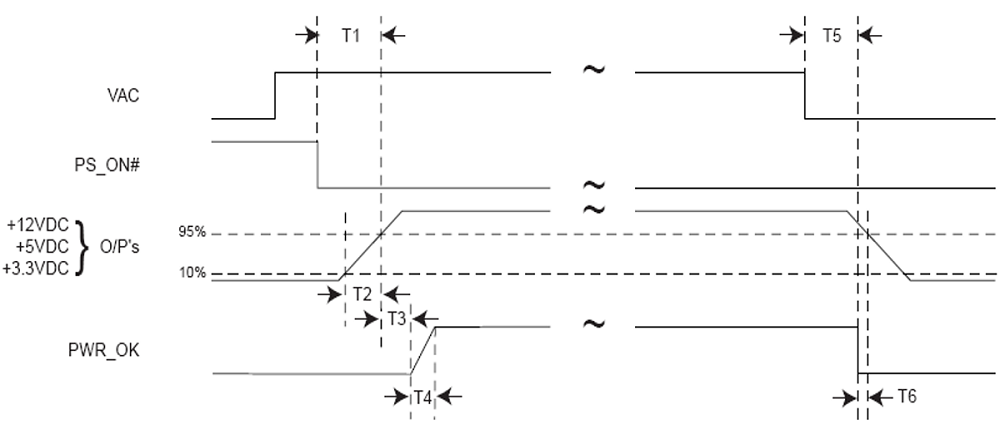
- Below you can see the timing diagram for the power good signal as available on the ATX12V specification. “VAC” is the input alternating voltage, i.e., the voltage from the wall. PS_ON# is the “power on” signal (i.e., you pushed the “standby” button from the computer case). “O/P’s” stand for “operating points.” And PWR_OK is the power good signal.
-

- Power-on Time (T1): The power-on time is defined as the time from when PS_ON# is pulled low to when the +12VDC, +5VDC, and +3.3VDC outputs are within the regulation ranges. The power-on time shall be less than 500 ms (T1 < 500 ms).
- Rise Time (T2): The output voltages shall rise from ≤10% of nominal to within the regulation ranges within 0.1 ms to 20 ms (0.1 ms ≤ T2 ≤ 20 ms).
- PWR_OK delay (T3): PWR_OK is a “power good” signal. It should be asserted high by the power supply to indicate that the +12VDC, +5VDC, and +3.3VDC outputs are above the under-voltage thresholds.
- Power-down warning (T6): During power-down, the PWR_OK signal should be asserted low at least 1ms before the +12VDC, +5VDC, and +3.3VDC outputs reach their under-voltage thresholds (T6 ≥ 1ms).
The tester displays N/A for some of the timing values. What does it mean?
- “N/A” means some of the timings are not yet measured. Timings are calculated during power-up and power-down process, so if it shows “N/A”, that means one or two power cycles are required to calculate the timings.
How does the tester measure ripple voltage?
- The Inline PSU tester samples the voltage on each rail at 10K samples per second. It then takes 1 second of data and searches for the absolute minimum and maximum voltage of each rail, every second. The min/max difference is reported as ripple. The voltage measurement precision in our tester is +-4 mV, so in the case of a small ripple (around that 4mV level), there will be measurement errors due to quantization error in the A/DC.
- Please note: Ripple measurement in the ATX Standard is not well defined. This lack of a defined specification leads to several different test methods and thus different results. What the ATX Standard does specify is that ripple should be measured at 20MHz bandwidth with 0.1uF ceramic disk capacitor and a 10uF electrolytic capacitor to simulate system loading, and the PSUTester meets these specifications.
Does the device need to be connected to a PC via the USB port?
- No. The PSU Tester can be powered up via the 24-Pin connector. However, the voltage reference and the protection circuits in the PSU Tester rely on the 5V input voltage. Therefore, if the +5V rail fails to provide a clean and accurate voltage that could affect the accuracy of the measurements and the functionality of the protection circuits. For that reason, we recommend connecting the USB port to a PC or a wall charger.
Can I measure the efficiency of a PSU using the PSU Tester?
- Yes. Measuring efficiency is all about accurately measuring the input power and the output power. The PSU tester can measure the output power. For measuring the input power, a good quality power meter is also required.
Why the tester turns off the PSU after one minute in the standalone mode?
- In standalone mode the tester will dissipate 4Watts of power (in order to place a test load on the PSU). This can result in the base of the tester becoming warm to touch after a short period of time. The tester will automatically terminate testing after 1 minute to avoid overheating.
Can I only connect some of the connectors?
- The 24-pin input cable should always be connected to provide the reference ground needed for voltage measurement. Connecting other cables without a ground reference can damage the tester. The only exception is when the PCS Tester is used to test a machine with more than one GPU. See below "Can machines with multiple GPUs be tested?".
Can machines with multiple CPU/GPUs be tested?
-
The below document explains how to test machines with multiple CPU/GPUs.
https://www.passmark.com/downloads/TestingMultipleGPUs.pdf
My GPU has two power connectors, what should I do?
- The tester has one PCIe 6+2 output. However, you can use a y splitter with high end dual plug GPUs. 16AWG is the preferred wiring gauge (instead of 18AWG) and the cable should be made of high current (HCS) pins. It is also important to make sure all connectors are fully inserted to minimize electrical resistance.
-

Is it safe to use a y spliter to split the PCIe 6+2 pin cable into two PCIe 6+2 pin cable?
-
A 6 pin PCIe cable provides 75 watts and an 8 pin can provide 150 watts, so it doesn't seem to be a good idea to split the cable. But before drawing the conclusion, let’s do some math.
The PCI-E connecter has 6 pins. They are not all used for power. For the 6-pin connector, Pins 1 & 3 are 12V & each can carry 8 Amps. Pin 2 by spec is not connected, although most PSU manufacturers do add a 12V line there. Pins 4 & 6 are common return lines. Pin 5 is ground for sensing. Using 2 lines with standard pins, you get 12V*8A*2= 192 Watts, therefore the actual limit is a lot higher than the artificial limits (75 Watts). Since March 2005, the molex pins are required to be "HCS" rather than "Std", which each carry a max of 11Amps. So properly made, a 6 pin PCI-e cable can supply 12V*11Amps*3lines=396 Watts of power for the graphic cards. The output cable that comes with the tester is made by Plus HCS pins with 16AWG wires and rated for 13A. So, assuming reasonable quality cables are being used and there are only 2 current carrying 12V wires, you can use a splitter with high end dual plug GPUs for short term use. Quality splitters can be used safely when there are three current carrying wires in the PSU cable.
What information in included in the log file and report file?
- The log file contains the samples of voltage, current, power and ripple of different power rails at time intervals configured by the user (1, 10, 30 and 60 seconds). See here for an example of the log file.
- The report file contains voltage, current, power, ripple and timings for each power rail. The report also includes the total power drawn from the PSU and an overall Pass/Fail for voltages and timings. See here for an example of the report file.
Do I need a device driver to use the PSU Tester?
- For Windows 7 and 8, you need a device driver. For Windows 10, the usage of the native inbox driver (Microsoft driver) is recommended.
Is there a Linux driver for the device?
- Not at this time.
Is there an SDK / API to use the device from my own software?
- Not at this time.
The PSU Tester shows 0 volt for all voltages after firmware update. What should I do?
- This is a known issue that happens when updating firmware from version 1.0 to 1.3. Following the below steps fixes the problem.
- - Connect the tester to a PC using the USB cable
- - Run the PSUTest software
- - Click on "Calibration" to open the calibration window
- - Click on "Reset all calibration data"
- - Click on "OK" to close the calibration window
- - Remove and reconnect the device